A project from '19. It was interesting to learn about refractor alignment and construction and to get a possibly lightweight tube.
(Autotranslated with www.DeepL.com/Translator)
Lens
Ahromat 80/500 from ali. The lenses are green, multi-layered on all surfaces. The edge is clipped, I had to aperture the outermost millimeter. Correction shifted to the short-wave part of the spectrum - edge of the moon in defocus red-violet ⇔ green, instead of the more common blue-violet ⇔ yellow-green.
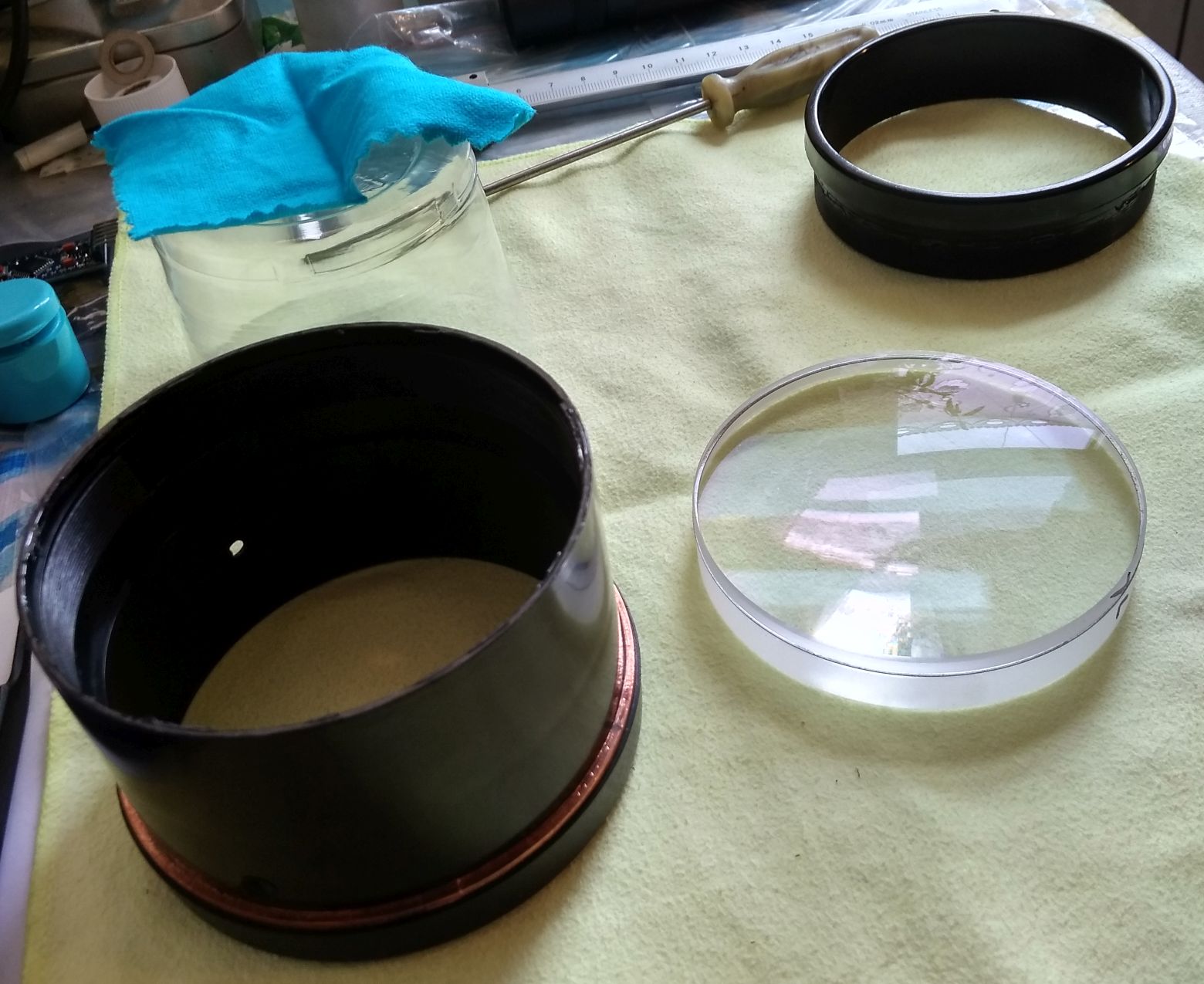
A suitably sized plastic cup covered with a lint-free cloth can be used to fit the lenses into the frame. If there are no marks on the end of the lenses, you should put tick marks there (turning the lenses upside down will cause a large spherical aberration, and turns may cause astigmatism).
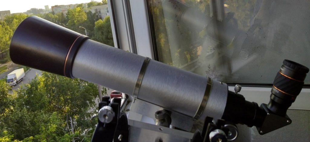
Tube
Glued together from absorbent cotton and epoxy using classical technology. The length of the tube is 33 cm. The thickness should be about 1 mm, i.e. you need 5 turns of batman. This is also sufficient for threading M3.
The adapter for screwing in the focuser is also glued from absorbent cotton with epoxy. The holder for the focuser is assembled from two types of "parts" - a flat ring, tightly screwed on the thread and a part to be inserted into the pipe (cut a triangle on the edge and bend it so it does not reach the thread a bit). Each part is 0.4 mm thick, made of two layers of wadding. Parts alternate, you need a dozen, the length of threads. Those to the pipe, sealed with superglue on the diameter to tightly assemble and signed. Then you need to epoxy all of them, assemble, put polyethylene on top and underneath and press with something heavy. In about 18 hours, when the epoxy is not quite hardened, we screw in the focuser, and if it screws in, we add sealant/superglue to the threads. And we attach it to the pipe by drilling holes and cutting M4 threads.
Paint the inside with black matte paint and wait for it to dry. Repeat.
Install 3-4 cardboard or plastic diaphragms inside the tube. They should not be thick, otherwise the edges can glare. Determine the size using the graphical method. When installing, look into the focuser in the working position and check that the lens is fully visible and the apertures do not cut it.
After that the weakest place will be the focuser tube, if you want it can be glued with flock.
The rings used are sanitary "butterfly clamp" rings. Attached by a pair of M4 screws, each to a flipper. The inside is glued with rubber self-adhesive.
The weight of the tube in the rings and with a simple eyepiece is about 1 kg.
Focuser
Metal rack and pinion from svbony. The backlash in it is somehow removed by adjusting screws (at the top, hexagonal), but it turned out that it is better to increase the thickness of the Teflon gaskets. They are self-adhesive, so you just have to take off a couple of the lower ones, stick a strip of tape in that place (60 microns was too much, 40 is just right) and glue the Teflon ones on top.
Refractor alignment
First, you must set the focuser so that it is parallel to the optical axis of the lens - the focuser itself is placed as flat as possible in the tube, the lens is covered with a cap (preferably with a hole in the center), the Cheshire eyepiece is directed to the light and by slight tilting of the lens the flare in the Cheshire is reduced to one (the error gives astigmatism).
It is better to check without the diagonal, it can introduce an error, which will be visible if you twist it.

The alternative method of the Maksutov cross and alignment in general, is well described in the 2015-12 journal Nebosvod 2015-12 - "On the improvement of inexpensive amateur refractor telescopes".
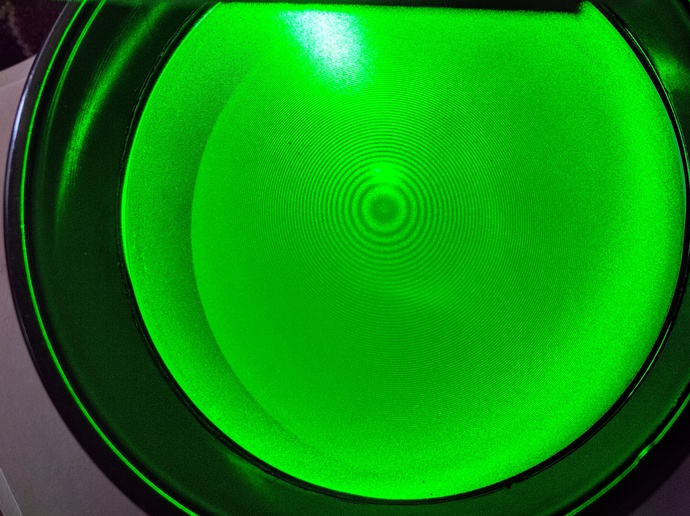
Then it is checked that the gaskets in the lens are of equal thickness. This is done with a laser pointer through something scattering, like a cloth. The newton rings should be in the center of the lens. (The error gives a coma and a traffic light). The method works when the interlens spacing is less than 0.3 mm (when greater, you only have to control the spacers with a micrometer).
Next, we make an artificial star - take a few pieces of foil, put it on the glass and pierce it with a sharp needle. Choose the foil with the dimmest hole and put it in front of the flashlight (preferably in a suitable cover to be put on the body of the flashlight). Then from a distance of about 20 focal lengths (you can get closer, but there will be additional uncorrected spherical aberration - the dofocal is sharper, the dofocal is cloudier) we look at this artificial star through the telescope. The focuser will need to be moved out about five centimeters. Magnification to put a large, about 2D.

You should make sure that the out-of-focus focal points are the same, circular, and both out-of-focus focal points show rings. And in focus a point is a point, there is no skew and cross astigmatism. The number of rings is not much of a concern, it depends on the brightness of the star.
The spherical aberration is adjusted by changing the thickness of the spacers. If the intrafocal is sharper and the extrafocal is cloudier, then the spherical aberration is uncorrected and the thickness of the spacers should be reduced in steps of about one hundred microns, and in the opposite case, the thickness of the spacers should be increased.
The normal thickness of the interlens ring is 250 microns, the thickness of normal printer paper is 100 microns, magazine paper is 70 microns. Do not make spacers thinner than 50 microns, otherwise the lenses will touch in the center. The ring is easiest to cut with a circular cutter from stationery (if the paper is thin, you need to glue it with the center to the cardboard so it doesn't crumple).
You can use three separate spacers instead of the ring, but you shouldn't make them too small - with them the lens is already more sensitive to astigmatism due to overcompression than with the ring.
If the out-of-focal lengths are noticeably different, it wouldn't hurt to put a 2-3 mm aperture ring on the lens before changing the thickness of the spacers to make sure it's not a matter of a swollen edge of the lens.
Astigmatism can be corrected by rotating the lens, or if not, by tilting the entire frame.
The coma can be removed by accurate lens positioning - there should be no lens tilt or cross shift. You can use three paper strips when installing the lenses to choose the gap between the lens and the frame. If that doesn't work - loosen the lenses, shake the lens, screw in. It may take several attempts, especially if the interlens gasket is very thick.
If there is no split ring or rubber ring in the frame, it should be added (before the first lens). A (at least paper) ring should be put on top of it - it will prevent the lenses from twisting when the lens frame is twisted. This reduces the risk of the lens getting jammed in the cold and makes alignment easier - the ring squeezes the lens to the center.
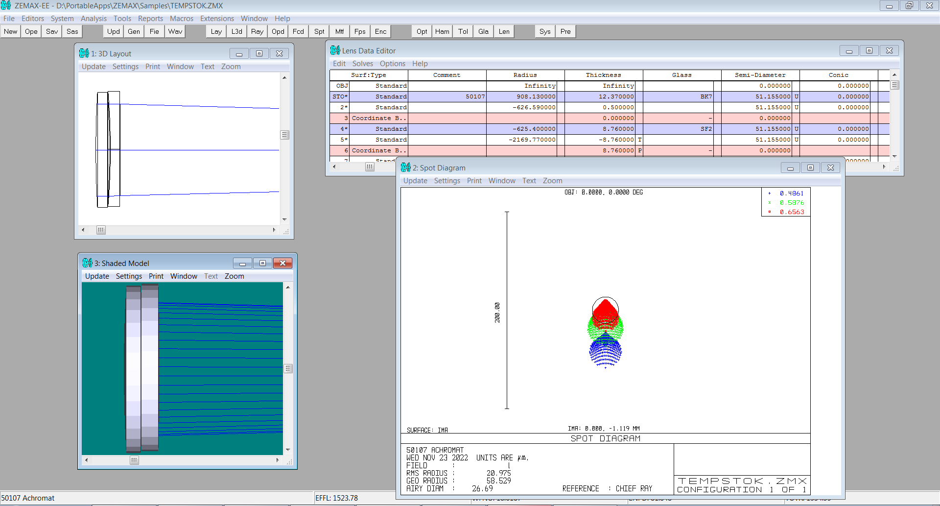
How alignment errors look in the simulator
Using the long achromat and zemax as examples.
Tilting of the second lens by 0.2 mm causes coma (Fig. 1), de-centering of the lens by 1 mm causes stoplight (Fig. 2), tilting of the whole lens by 1 mm causes astigmatism (Fig. 3).
From this you can see the required precision of installation - about 0.01 mm for the interlens distance, a little more for lens shift (they also tilt) and 0.1 mm for lens tilt as a whole.


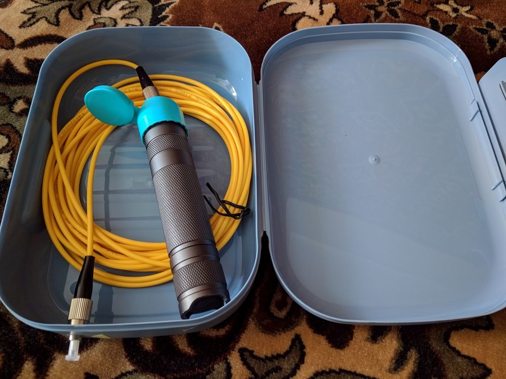
Artificial star
The size of the hole I got by piercing the foil was 30×40 microns, which is still just enough for an 80 mm lens from 7 meters, but if you want more, it is better to make an artificial star from fiber optics.
You need a 9/125 patch cord (this is the thickness of the fiber/shell in microns) for example, from Ozon, коробка (тут ланч-бокс за 30 рэ), фонарик с регулировкой яркости (тут convoy s2+) и подходящая крышка для их соединения.
The box is mandatory because of the narrow beam - at a deviation of 10 degrees, the brightness of the artificial star drops dramatically.
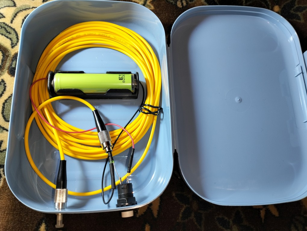
Alternatively, you can use a green LED, it gives a clearer picture when testing ED refractors. It is desirable to use a super-bright LED (the Chinese noname with 20 mA brightness is enough only in the evening; it is also undesirable to use lasers). Connection of LED with patchcord by heat shrink, 18650 power supply, 200 ohm resistor (or better 50 ohm + variable 1kOhm).
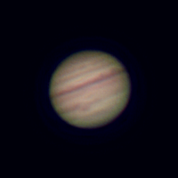
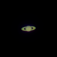
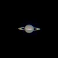
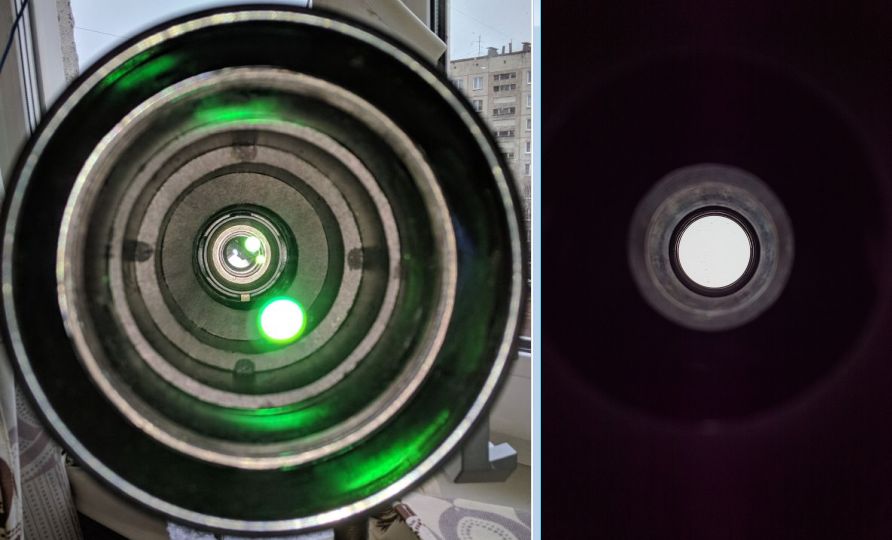
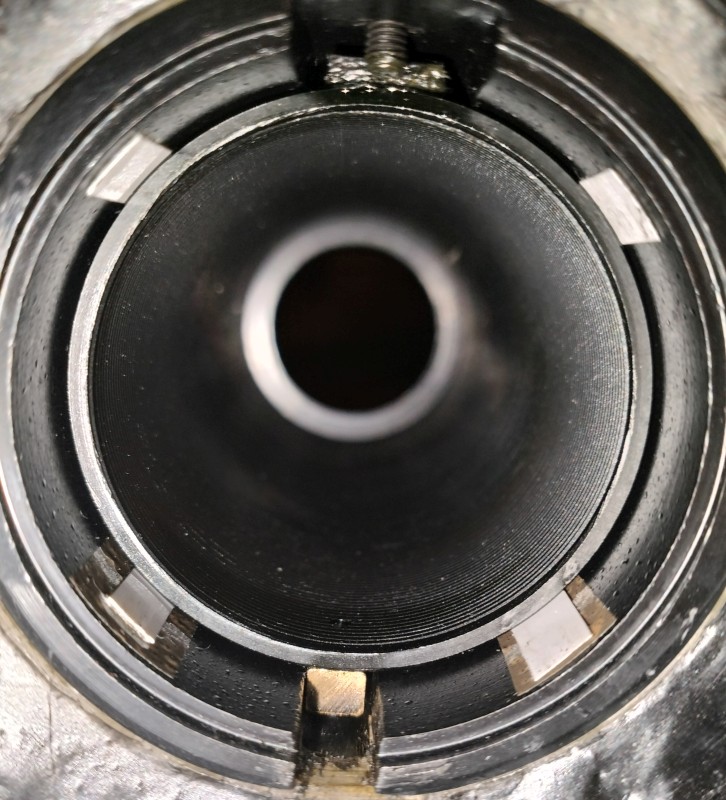
A few example photos
The first two on a handheld smartphone in '21, the third on an astro camera in '23.